Vehicle dynamics for a Formula Student car, 3rd at Formula Bharat 2020
Two seasons on a combustion Formula Student car's suspension and vehicle dynamics, from tyre data to track testing. In the second season I ran the vehicle-dynamics group.
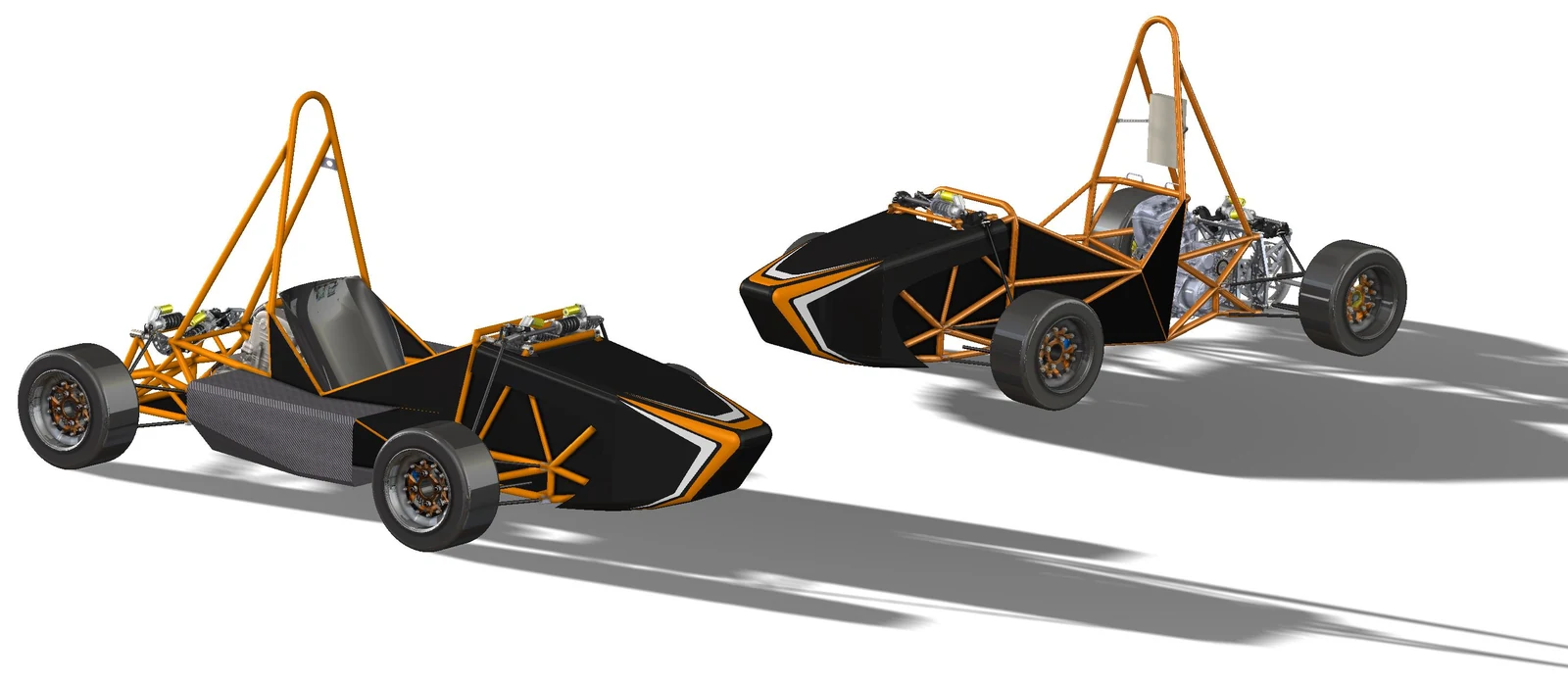
- Fig.
- 1
- Title
- The team's 2020 car and the 2021 design, in CAD
- Kind
- CAD render
- Source
- GTU Motorsports, Formula Student
- Role
- Vehicle Dynamics Engineer
- Team
- GTU Motorsports, about 25
- Period
- Apr 2019 to Mar 2021
- Team results
- Formula Bharat 2020, 3rd overall with 745 points, full marks in Acceleration and Endurance; Formula Bharat 2021 (held virtually), 5th overall, 3rd in Engineering Design
- Suspension
- About 3 kg removed, part by part
- Tools
- SolidWorks, ANSYS Workbench, MSC Adams, Lotus Suspension Analysis, Excel


Fig. 2 · Records: the organiser's certificates, 2020 and 2021


Two seasons
I worked on the car's suspension and vehicle dynamics for two seasons, on the 2020 car and the 2021 design (Fig. 1). The decoupled heave and roll suspension was designed for both and ran on track at Formula Bharat 2020; Formula Bharat 2021 was held virtually, and I defended the vehicle-dynamics design to the Engineering Design judges. The organiser's certificates from both events are with the team's results in the title block (Fig. 2).
The team's first decoupled suspension
I designed the team's first suspension with independent heave and roll springs and dampers, with no reference design to follow (Fig. 3). Fig. 4 shows the split: rockers drive a heave element when the wheels move together and a roll element when they move in opposition, so heave and roll each get their own stiffness and damping.
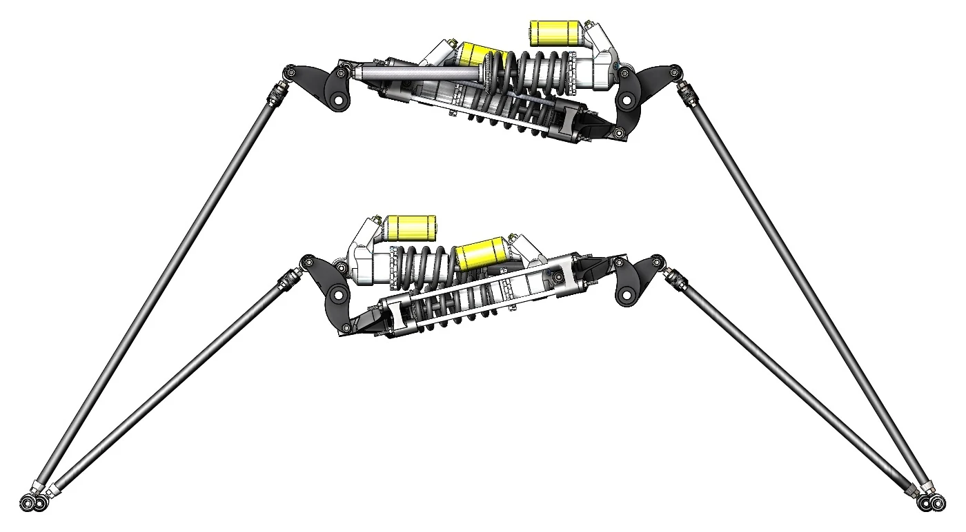
- Fig.
- 3
- Title
- The heave and roll units with their pushrods, in CAD
- Kind
- CAD render
- Source
- GTU Motorsports, Formula Student
- Fig.
- 4
- Title
- Heave and roll, decoupled
- Kind
- Schematic, principle only, not to scale
- Source
- Drawn for this site
- Note
- In the accent, the element that works in each case. The roll element is the unit in the damper cage.
- Fig.
- 5
- Title
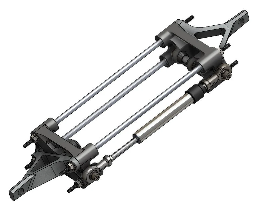
- The damper cage: one spring-damper held between two yokes on four guide rods, loaded in compression whether the rocker pushes or pulls
- Kind
- CAD render
- Source
- GTU Motorsports, Formula Student
The roll damper is mounted so that it compresses in roll one way and extends in roll the other. A damper works both ways, but a spring only pushes back in compression, so I designed a cage that always compresses the spring-damper, whether the rocker pulls it apart or pushes it together (Fig. 5).
Major parts in FEA
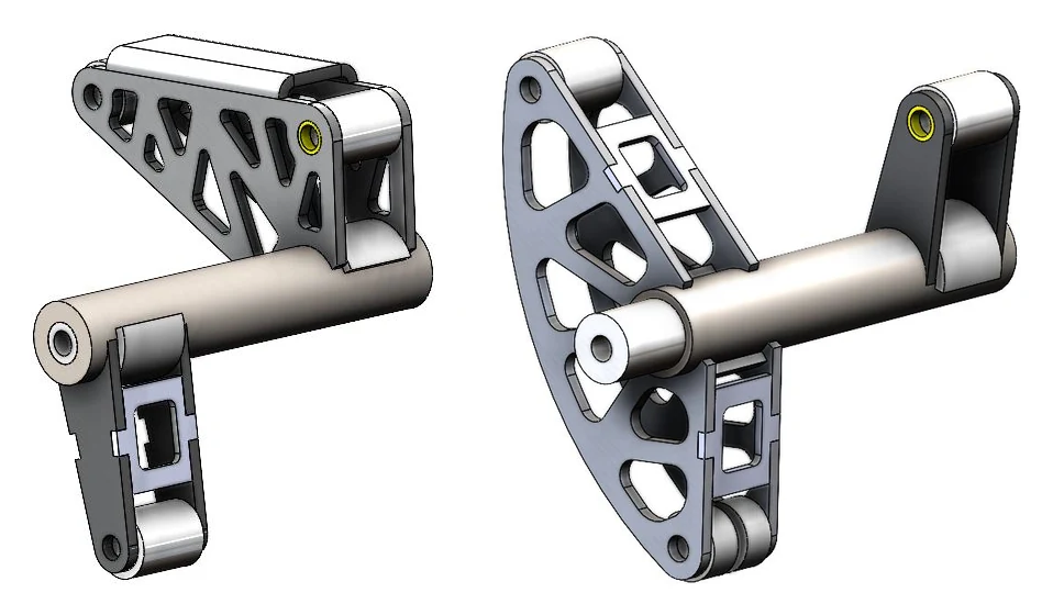
I ran FEA on every major suspension part, 5 to 10 load cases each, before it was made. The heave and roll rockers show the sequence: designed on their shafts in CAD (Fig. 6), checked in FEA under the maximum heave and roll spring forces at the element eyes (Fig. 7), and held in position for welding by a fixture (Fig. 8).
- Fig.
- 6
- Title
- The heave and roll rockers on their shafts
- Kind
- CAD render
- Source
- GTU Motorsports, Formula Student
- Note
- Same order as the FEA; the CAD and the FEA model differ in detail at the shaft ends.
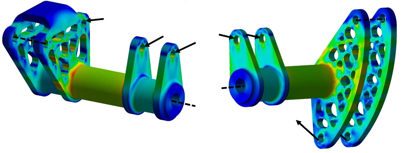
- Fig.
- 7
- Title
- Heave and roll rockers in FEA
- Kind
- FEA, stress contour, scale removed
- Source
- GTU Motorsports, Formula Student
- Note
- Load case: the maximum heave and roll spring forces at the element eyes. Colour shows stress; values withheld.
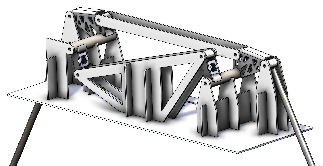
- Fig.
- 8
- Title
- Welding fixture for the rocker assembly
- Kind
- CAD render
- Source
- GTU Motorsports, Formula Student
Part by part, in many small steps, this took about 3 kg out of a suspension that was already light: the wheel centres, the damper cage, the damper extension shaft and the rocker shafts.
A blade anti-roll bar
For the same layout I designed a blade anti-roll bar, so roll stiffness can be retuned in minutes with the same parts. Fig. 9 is the bar in CAD and one blade arm in FEA, flat and turned; Fig. 10 is why turning it works: flat, the blade bends about its thin side and is soft, on edge about its wide side and is stiff.
The plates at the blade roots set the angle (Fig. 11), and FEA at three positions, the two extremes and the middle, found the limits of its roll-stiffness range.
The blade bar and the caged roll spring are two ways to give the car its roll stiffness: the bar for a layout with plain dampers on the rocker shafts, the cage for a roll spring-damper. One or the other, never both.
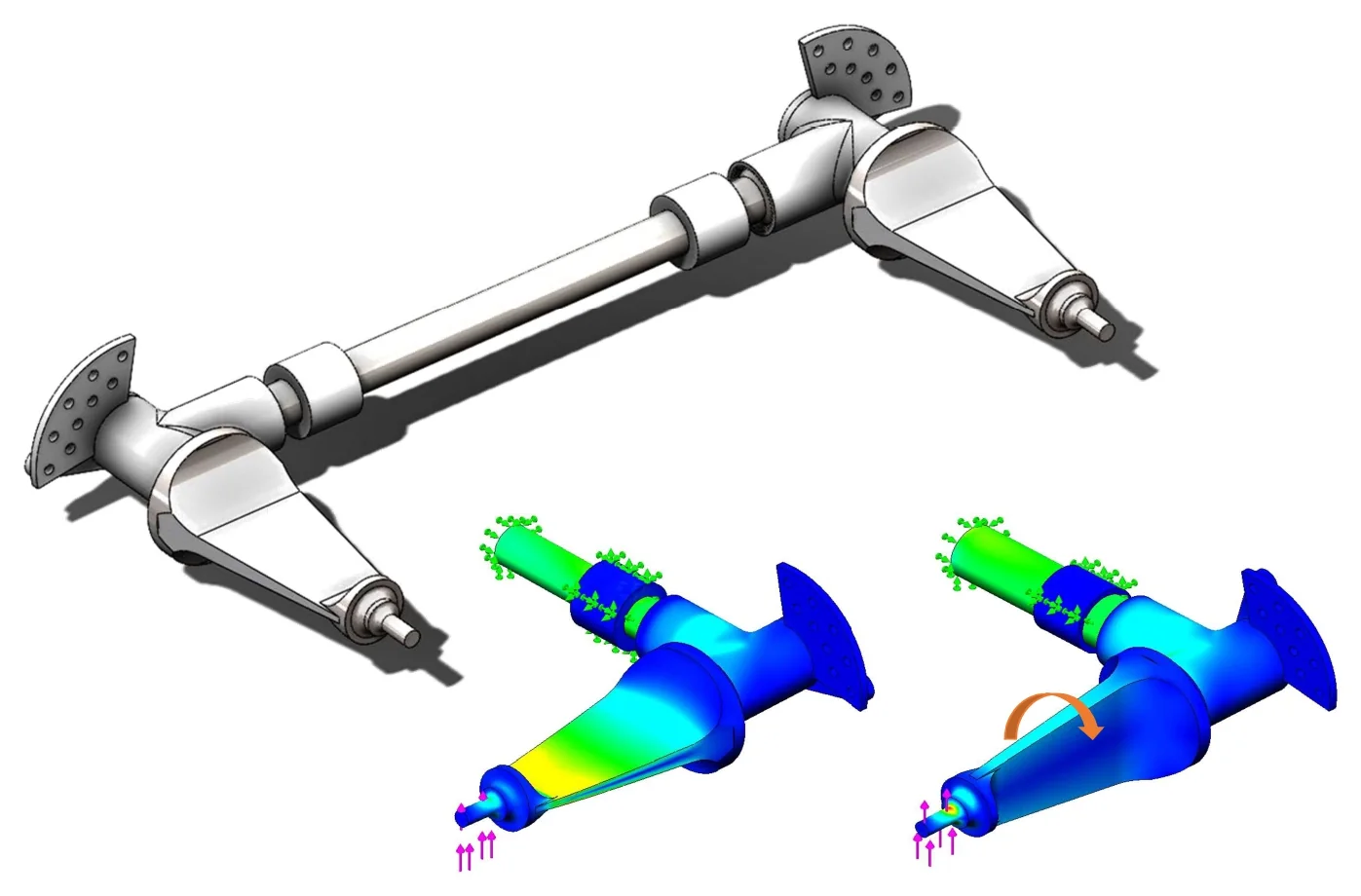
- Fig.
- 9
- Title
- Blade anti-roll bar in CAD, and the blade arm in FEA with the blade flat and turned
- Kind
- CAD render; FEA, stress contour, scale removed
- Source
- GTU Motorsports, Formula Student
- Note
- Fixed at the bar, loaded at the blade tip. Colour runs from blue, low stress, to red, high; values withheld.
- Fig.
- 10
- Title
- The blade bar in plan, and the blade in section
- Kind
- Schematic, principle only, not to scale
- Source
- Drawn for this site
- Note
- b: blade width; t: blade thickness. Bending axis dash-dot, load in copper.
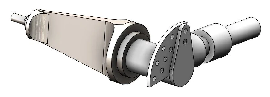
- Fig.
- 11
- Title
- The blade arm and the plates that set its angle
- Kind
- CAD render
- Source
- GTU Motorsports, Formula Student
More depth: the bars it replaces, the sizing and the strength load cases
The rear bulkhead
With the chassis department I co-designed the rear bulkhead: a water-jet plate assembly that carries the suspension and drivetrain mounts. It was designed to stiffen the rear in torsion and shorten the car's frame. Fig. 12 is the assembly in CAD, with the rockers, the spring-dampers and the drive it carries; Fig. 13 is the 2021 design it belongs to.
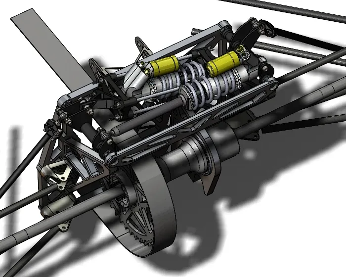
- Fig.
- 12
- Title
- The rear bulkhead assembly I co-designed with the chassis department, in CAD: the plates that carry the rockers, the spring-dampers and the drive
- Kind
- CAD render, cropped
- Source
- GTU Motorsports, Formula Student
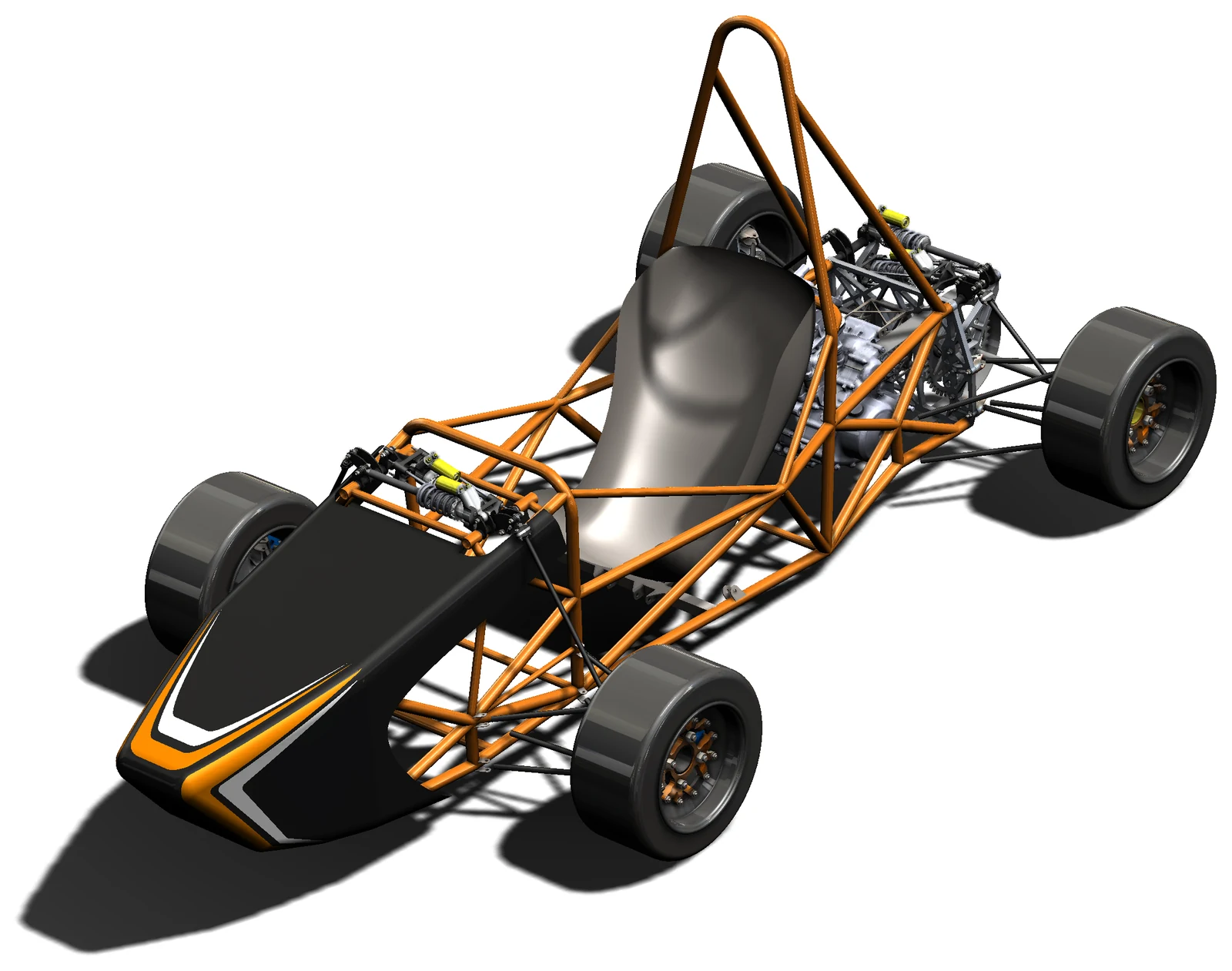
- Fig.
- 13
- Title
- The 2021 design in CAD
- Kind
- CAD render
- Source
- GTU Motorsports, Formula Student
Tyre data
When the team's attempt in MATLAB stalled, I analysed the Formula SAE Tire Test Consortium data in Excel for one question: how much grip the tyres gain or lose at each level of weight transfer. Fig. 14 is the relation, not the data: two tyres sharing a load make more side force than the same two once load moves from one to the other.
The suspension and its load cases were set to manage that transfer in cornering, and I left the workflow so later team members could reuse it.
- Fig.
- 14
- Title
- Why weight transfer costs grip
- Kind
- Relation, not data
- Source
- Drawn for this site
- Note
- Tyre data are licensed to Tire Test Consortium members and are not shown.
Testing and setup
I planned the instrumentation in Fig. 15: damper potentiometers on the heave and roll units, steering angle, an IMU and wheel speed, with scale pads for corner weights; the key says what each one was for.
On track I ran the setup work against the model's targets: corner weights, and bump and rebound settings for the heave and roll dampers.
| Sensor | Measures | Used for |
|---|---|---|
| 1Damper potentiometers, heave and roll units | Damper travel and velocity | Damping settings; heave travel for ride height |
| 2Steering angle | The driver's steering input | Reading the car's response against the input |
| 3IMU, near the centre of gravity | Lateral acceleration and roll angle | The roll gradient |
| 4Wheel speed, at the uprights | Speed of each wheel | Vehicle speed |
| 5Scale pads, one under each wheel | The load on each wheel | Corner weights |
- Fig.
- 15
- Title
- Sensor plan
- Kind
- Schematic, principle only, not to scale
- Source
- Drawn for this site
Running the group
I split the group's work, two engineers on a team of about 25, across suspension design, tyre analysis and steering; ran the design reviews and the simulation and FEA checks; coordinated with the chassis, powertrain, steering and braking groups; and trained team members in ANSYS and Adams.