Vehicle Dynamics Engineer · GTU Motorsports, Formula Student · Apr 2019 to Mar 2021
A decoupled heave and roll suspension that ran at Formula Bharat 2020
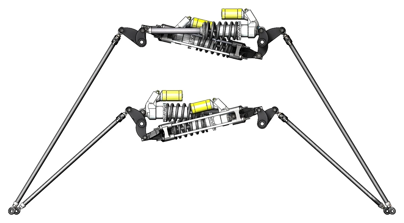
- Fig.
- 1
- Title
- The heave and roll units with their pushrods, in CAD
- Kind
- CAD render
- Source
- GTU Motorsports, Formula Student
Problem
With four corner spring-dampers, one set of springs and dampers carries both heave and roll, so a setting that suits one compromises the other. A decoupled layout gives each mode its own spring and damper, so heave and roll stiffness and damping can be set independently. Nobody in the team had built one.
Approach
Rockers split the motion: a heave element works when the wheels move together, a roll element when they move in opposition (Fig. 2), each with its own motion ratio. I placed the geometry in a full-car MSC Adams model and set the two ratios there (Fig. 1). For the roll element I designed a damper cage that always compresses its spring-damper, whether the rocker pulls it apart or pushes it together (Fig. 3).
- Fig.
- 2
- Title
- Heave and roll, decoupled
- Kind
- Schematic, principle only, not to scale
- Source
- Drawn for this site
- Note
- In the accent, the element that works in each case. The roll element is the unit in the damper cage.
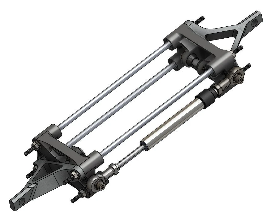
- Fig.
- 3
- Title
- The damper cage: one spring-damper held between two yokes on four guide rods, loaded in compression whether the rocker pushes or pulls
- Kind
- CAD render
- Source
- GTU Motorsports, Formula Student
What I did
- Designed the decoupled layout, with independent heave and roll damping.
- Designed the damper cage, so a standard spring-damper gives the roll stiffness in both directions of roll, and a later iteration on linear bearings and low-friction joints, for more precise motion.
- Built the full-car kinematic model in MSC Adams from scratch, because no template supported the geometry, cross-checked it in Lotus Suspension Analysis, and used it to set roll-centre migration, camber gain, bump steer and motion ratios.
- Ran FEA on every major suspension part, from the rockers and uprights to the wheel centres, across 5 to 10 load cases each: maximum cornering, braking, acceleration, heave and combined (Figs. 4 and 5).
- Took mass out of the unsprung wheel centres and, inboard, the damper cage, the damper extension shaft and the rocker shafts.
- Designed the welding fixtures (Fig. 6); the team did its own part design, design for manufacture, bearing and fastener selection.
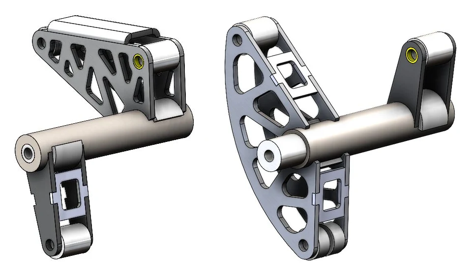
- Fig.
- 4
- Title
- The heave and roll rockers on their shafts
- Kind
- CAD render
- Source
- GTU Motorsports, Formula Student
- Note
- Same order as the FEA; the CAD and the FEA model differ in detail at the shaft ends.
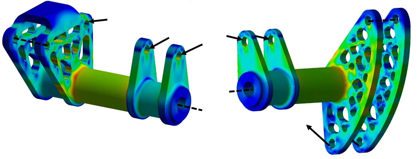
- Fig.
- 5
- Title
- Heave and roll rockers in FEA
- Kind
- FEA, stress contour, scale removed
- Source
- GTU Motorsports, Formula Student
- Note
- Load case: the maximum heave and roll spring forces at the element eyes. Colour shows stress; values withheld.
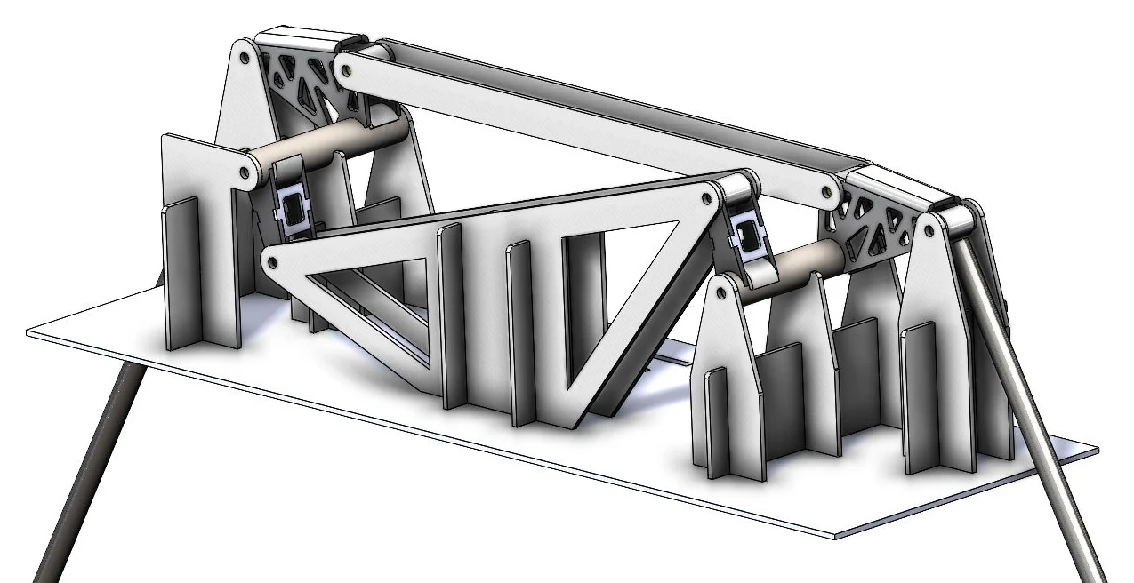
- Fig.
- 6
- Title
- Welding fixture for the rocker assembly
- Kind
- CAD render
- Source
- GTU Motorsports, Formula Student
Result
- Ran on track at Formula Bharat 2020.
- About 3 kg out of parts that were already light, in many small steps.