Vehicle Dynamics Engineer · GTU Motorsports, Formula Student · Apr 2019 to Mar 2021
A blade anti-roll bar designed to be retuned in minutes
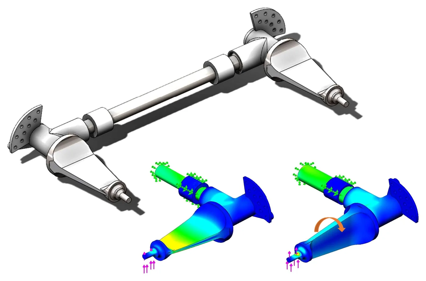
- Fig.
- 1
- Title
- Blade anti-roll bar in CAD, and the blade arm in FEA with the blade flat and turned
- Kind
- CAD render; FEA, stress contour, scale removed
- Source
- GTU Motorsports, Formula Student
- Note
- Fixed at the bar, loaded at the blade tip. Colour runs from blue, low stress, to red, high; values withheld.
Problem
The team's earlier anti-roll bars had a fixed diameter: a different roll stiffness meant a different bar.
Approach
I designed a blade-type bar instead. The blade is a flat beam, stiff on edge and soft when flat, so turning it changes the bar's rate with the same parts (Fig. 2). I checked it in FEA at three blade positions, the two extremes and the middle, to find the limits of its roll-stiffness range (Fig. 1). The blade bar and the caged roll spring are two ways to give the car its roll stiffness: the bar for a layout with plain dampers on the rocker shafts, the cage for a roll spring-damper. One or the other, never both.
- Fig.
- 2
- Title
- The blade bar in plan, and the blade in section
- Kind
- Schematic, principle only, not to scale
- Source
- Drawn for this site
- Note
- b: blade width; t: blade thickness. Bending axis dash-dot, load in copper.
What I did
- Designed the blade-type adjustable bar and its link to the heave and roll rockers, with plates that set the blade angle (Fig. 3).
- Sized it against the weight-transfer targets from the tyre data.
- Checked it in FEA for its strength under cornering, braking, acceleration and combined loads.
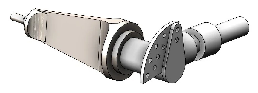
- Fig.
- 3
- Title
- The blade arm and the plates that set its angle
- Kind
- CAD render
- Source
- GTU Motorsports, Formula Student
Result
- A bar designed so roll stiffness can be retuned in minutes, with the limits of its stiffness range known from FEA.