Vehicle Dynamics Engineer · GTU Motorsports, Formula Student · Apr 2019 to Mar 2021
A damper cage that always compresses the roll spring
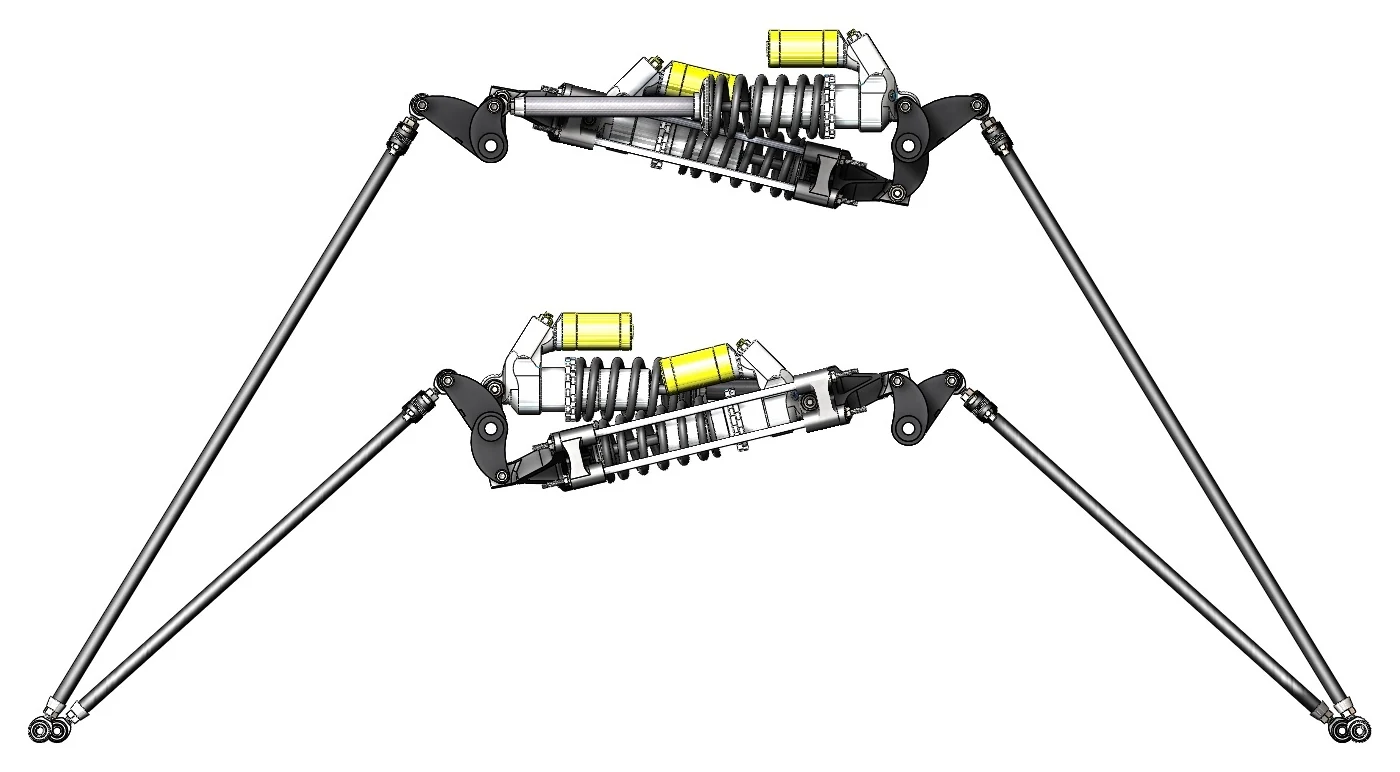
- Fig.
- 1
- Title
- The heave and roll units with their pushrods, in CAD
- Kind
- CAD render
- Source
- GTU Motorsports, Formula Student
Problem
The roll damper sits inclined between the two rockers. In roll one way it compresses; in roll the other way it extends. A damper resists both, but a spring pushes back only when it is compressed, so on its own the roll spring would hold the car in one direction of roll and not the other.
Approach
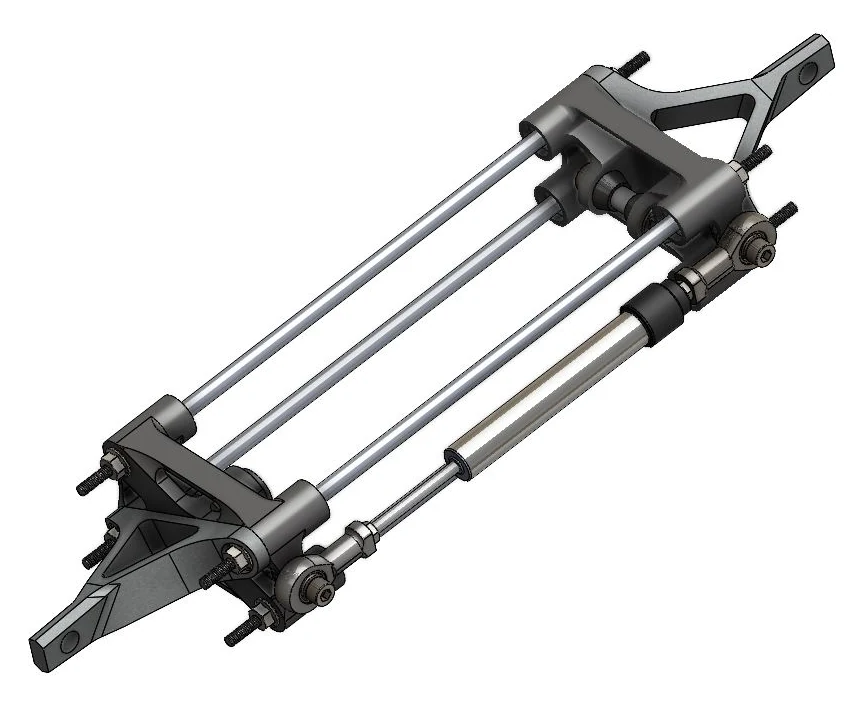
I designed a cage around the spring-damper: two yokes on four guide rods. However the rockers move the cage, pulling it apart or pushing it together, the yokes compress the spring-damper inside (Fig. 2). The roll spring works in both directions, and the unit fits where a conventional layout did not.
- Fig.
- 2
- Title
- Why the cage: the roll spring-damper without and with it
- Kind
- Schematic, principle only, not to scale
- Source
- Drawn for this site
- Note
- Phantom: at rest; solid: displaced; the spring in the accent. The yokes are drawn as plates and rods, not to their shape; the CAD shows the real cage.
What I did
- Designed the cage: two end yokes on four guide rods, with the spring-damper and its rod ends held between them (Fig. 3).
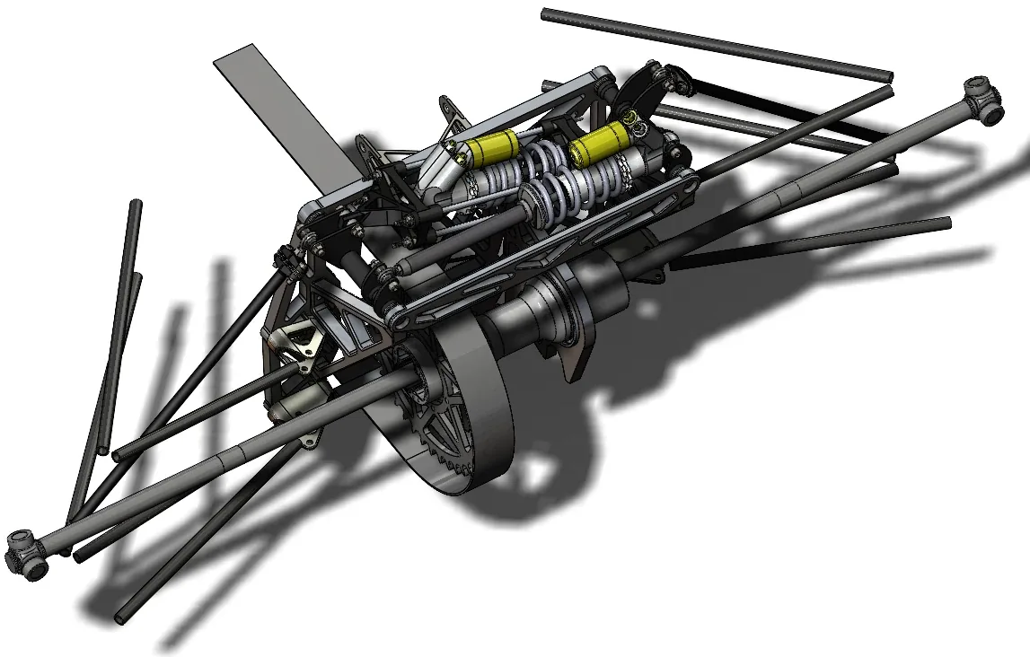
- Placed it between the rockers, beside the heave spring-damper (Fig. 4).
- Designed a later iteration on linear bearings and low-friction joints, for more precise motion.
- Took mass out of the cage, one of many small steps on parts that were already light.
- Fig.
- 3
- Title
- The damper cage: one spring-damper held between two yokes on four guide rods, loaded in compression whether the rocker pushes or pulls
- Kind
- CAD render
- Source
- GTU Motorsports, Formula Student
- Fig.
- 4
- Title
- Where the cage sits in the 2021 design: the rear bulkhead assembly, in CAD
- Kind
- CAD render
- Source
- GTU Motorsports, Formula Student
Result
- Ran on track at Formula Bharat 2020, on the team's first decoupled heave and roll suspension.